Sensor node!

This tutorial demonstrates: a. howto create a mote with Raspberry Pi and Arduino b. howto use it
A sensor node, also known as a mote, is a node in a sensor network that is capable of performing some processing, gathering sensory information and communicating with other connected nodes
Create a mote with Raspberry Pi
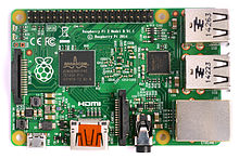
The Raspberry Pi is a low-cost credit-card sized single-board computer. The Raspberry Pi was created in the UK by the Raspberry Pi Foundation. The Raspberry Pi Foundation’s goal is to "advance the education of adults and children, particularly in the field of computers, computer science and related subjects."
|
Remember
A mote is a node but a node is not always a mote! 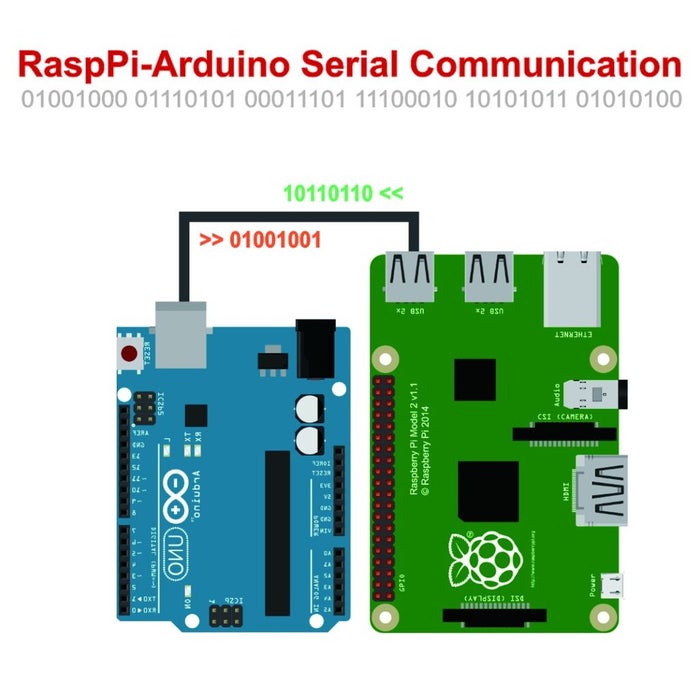
|
Install Raspberry Pi
Step 1: Download Raspbian
Download the Raspbian disc image - Choose Raspbian Lite
|
Why Raspbian Lite?
Because it is a lightweight version of the Raspbian and it doesn’t have a graphical user interface installed. This means that it doesn’t have any unnecessary software installed that we don’t need for our projects, so this makes it the perfect solution for future automation projects. |
Step 2: Unzip the file
-
Windows users, you’ll want 7-Zip.
-
Linux users will use the appropriately named Unzip.
Step 3: Write the disc image to your microSD card
Next, pop your microSD card into your computer and write the disc image to it. You’ll need a specific program to do this:
-
Windows users, your answer is Win32 Disk Imager.
-
Linux people, Etcher – which also works on Windows – is what the Raspberry Pi Foundation recommends
The process of actually writing the image will be slightly different across these programs, but it’s pretty self-explanatory no matter what you’re using.
-
Each of these programs will have you select the destination (make sure you’ve picked your microSD card!) and the disc image (the unzipped Raspbian file).
-
Choose, double-check, and then hit the button to write.
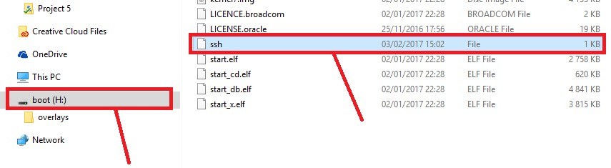
Step 4: Enabling SSH
-
Windows users
-
Linux Users
sudo fdisk -l
# find dev and Boot partition
sudo mkdir /mnt/sdcardP1
sudo mount /dev/device_partion_boot /mnt/sdcardP1 -rw
cd /mnt/sdcardP1
sudo touch ssh
Step 5: Put the microSD card in your Pi and boot up
Your default credentials are username pi and password raspberry
Step 6: Access via SSH
-
The boot protocol for the ethernet interface is set to DHCP by default
You can find the open SSH ports on your network using the nmap utility:
nmap -p 22 --open -sV 192.168.1.0/24You should find your pi listed in the output along with the IP assigned to the pi.
-
You can change the boot protocol to static and define a static IP address for the pi by editing the ifcfg-eth0 file:
sudo fdisk -l
# find dev and Boot partition
sudo mkdir /mnt/sdcardP1
sudo mount /dev/device_partion_ext /mnt/sdcardP1 -rw
cd /mnt/sdcardP1
vi /etc/sysconfig/network-scripts/ifcfg-eth0
Then edit the file to suit your needs
DEVICE=eth0
BOOTPROTO=static
ONBOOT=yes
NETWORK=192.168.1.0
NETMASK=255.255.255.0
IPADDR=192.168.1.200
GATEWAY=192.168.1.1
Step 7: Configure your Raspberry Pi.
raspi-config is the Raspberry Pi configuration tool
sudo raspi-configIt has the following options available:
┌──────────┤ Raspberry Pi Software Configuration Tool (raspi-config) ├─┐
│                                                                      │
│ 1 Change User Password Change password for the current user          │
│ 2 Network Options      Configure network settings                    │
│ 3 Boot Options         Configure options for start-up                │
│ 4 Localisation Options Set up language and regional settings         │
│ 5 Interfacing Options  Configure connections to peripherals          │
│ 6 Overclock            Configure overclocking for your Pi            │
│ 7 Advanced Options     Configure advanced settings                   │
│ 8 Update               Update this tool to the latest version        │
│ 9 About raspi-config   Information about this configuration tool     │
│                                                                      │
│                    <Select>                           <Finish>       │
│                                                                      │
└──────────────────────────────────────────────────────────────────────┘
Arduino Uno Raspberry Pi Serial Communication
Serial config on Raspi
whoami
sudo usermod -a -G dialout pi
reboot
This gives read/write permission for all users to the Raspberry Pi (potentially unsafe):
sudo chmod 777 /dev/ttyACM0This provides some configuration for the Arduino serial connection:
sudo stty -F /dev/ttyACM0 cs8 9600 ignbrk -brkint -icrnl -imaxbel -opost -onlcr -isig -icanon -iexten -echo -echoe -echok -echoctl -echoke noflsh -ixon -crtsctsReading in arduino
void loop() {
    meas = analogRead(a);
    if (Serial.available())
    {
        if (Serial.read() == '1')
        {
            Serial.println(meas);
        }
    }
}
Python
import serial
from datetime import datetime
from time import sleep
now = datetime.now()

ser = serial.Serial('/dev/ttyACM0', 9600)
ser.write("1".encode())
sleep(0.05);
s = ser.readline()

file = open("dataset", "a")
file.write(now.strftime("%Y-%m-%d %H:%M") + " Sensor Value:" + str(s)+ "\n")
file.close()
PHP
|
PHP Class
|
<?php

include "php_serial.class.php";

$serial = new phpSerial();
$serial->deviceSet("/dev/ttyACM0");
$serial->confBaudRate(9600);
$serial->confParity("none");
$serial->confCharacterLength(8);
$serial->confStopBits(1);
$serial->confFlowControl("none");

$serial->deviceOpen();
$read = $serial->readPort();
$serial->deviceClose();

echo $read
Sends a string to the Arduino.
<?php

error_reporting(E_ALL);
ini_set('display_errors', '1');
include "php_serial.class.php";

$serial = new phpSerial;
$serial->deviceSet("/dev/ttyAMA0");
$serial->confBaudRate(115200);
$serial->confParity("none");
$serial->confCharacterLength(8);
$serial->confStopBits(1);
$serial->deviceOpen();
$serial->sendMessage("Hello from my PHP script, say hi back!");

$serial->deviceClose();

echo "I've sended a message! \n\r";
NodeJS
|
Read the writing carefully on your Raspberry Pi circuit board to confirm it indicates something like “Raspberry Pi 4 Model B” or “Raspberry Pi 2 Model B”. If in doubt, run the following command in the terminal: $ uname -m If the result returned starts with “armv6”, you are running a Raspberry Pi based on the older ARMv6 chipset and the next Node.js installation step will not work; otherwise, you are ready for the next step. |
curl -sL https://deb.nodesource.com/setup_13.x | sudo -E bash -
sudo apt install -y nodejs
npm install raspi-serialcd ~
wget http://nodejs.org/dist/v6.2.1/node-v6.2.1-linux-armv6l.tar.gz
tar -xzf node-v6.2.1-linux-armv6l.tar.gz
cd node-v6.2.1-linux-armv6l/
sudo cp -R * /usr/local/
export PATH=$PATH:/usr/local/bin
npm install raspi-serialmport { init } from 'raspi';
import { Serial } from 'raspi-serial';
init(() => {
var serial = new Serial();
serial.open(() => {
serial.on('data', (data) => {
process.stdout.write(data);
});
serial.write('Hello from raspi-serial');
});
});Send data2server
NodeJS
...
var serverIOT=IP_SERVER
	const socket = require('socket.io-client')('https://'+serverIOT+':9080');
	socket.on('connect', function () {
		socket.emit('subscribe', log);
 		var obj = new Object();
   	obj.room = log;
   	obj.message  = data;
   	var text = JSON.stringify(obj);
		var text1 = Buffer.from(text);
		var text5 = text1.toString('base64');
		socket.emit('log', text5, log )
        //console.log(util.inspect(text5, false, null, true /* enable colors */))

    res.json({
        'message':"ok"
    });
	});

...How to communicate Arduino2Raspberry
Blinking example (*)
Arduino code
/*
 * serial_usb_simple_arduino - For communicating over USB serial. Send it a '1' (character one)
 * and it will make the builtin LED start blinking every one second. Send it a '0'
 * (character zero) and it will make it stop blinking.
 *
 * Each time it receives one of the commands, it sends back an 'A' for acknowledge.
 * But send it a commmand it doesn't recognize and it sends back an 'E' for error.
 */

bool blinking = false;
bool led_on = false;
int target_time;

void setup() {
  Serial.begin(115200);
  while (!Serial) {
    ; // wait for serial port to connect. Needed for native USB
  }
  pinMode(LED_BUILTIN, OUTPUT);
}

void loop() {
  char c;

  if (Serial.available() > 0) {
    c = Serial.read();
    switch (c) {
    case '0':
      // stop blinking
      blinking = false;
      if (led_on) {
        digitalWrite(LED_BUILTIN, LOW);
      }
      Serial.write("A", 1);
      break;
    case '1':
      // start blinking
      if (blinking == false) {
        blinking = true;
        digitalWrite(LED_BUILTIN, HIGH);
        led_on = true;
        target_time = millis() + 100; // turn off in 1 tenth of a second (100 milliseconds)
      }
      Serial.write("A", 1);
      break;
    default:
      Serial.write("E", 1);
      break;
    }
  } else if (blinking) {
    if (millis() >= target_time) {
      if (led_on) {
        digitalWrite(LED_BUILTIN, LOW);
        led_on = false;
        target_time = millis() + 100; // turn on in 1 tenth of a second (100 milliseconds)
      } else {
        digitalWrite(LED_BUILTIN, HIGH);
        led_on = true;
        target_time = millis() + 100; // turn off in 1 tenth of a second (100 milliseconds)
      }
    }
  }
}
Raspberry Pi C language
/*
 * serial_usb_simple - Demo that communicates over USB using serial I/O
 * from a Raspberry Pi to an Arduino.
 *
 * To show that it work, this writes a '1' to the Arduino which then
 * blinks the builtin LED on and off. The Arduino also sends back an 'A'
 * to acknowledge that it got the message. This does a read() to get
 * the 'A', demonstrating that reading also works. Two seconds later,
 * this writes a '0' to the Arduino which then stops the blinking.
 * The Arduino again sends back an 'A' to acknowledge that it got the
 * message and this reads the 'A'.
 *
 * This was tested between a Raspberry Pi 3B (running Raspbian) and
 * an Arduino Mega 2560 and also between an NVIDIA Jetson TX1 (running
 * Ubuntu) and the same Arduino.
*/

#include <errno.h>
#include <stdio.h>
#include <stdlib.h>
#include <string.h>
// for the serial I/O
#include <fcntl.h>
#include <termios.h>
#include <unistd.h>
#include <linux/serial.h>
#include <sys/ioctl.h>
#include <sys/stat.h>

int open_serial_port(char *name)
{
	int fd, bits;
	struct termios term;
	struct serial_struct kernel_serial_settings;

	if ((fd = open(name, O_RDWR | O_NONBLOCK | O_NOCTTY )) == -1) {
		fprintf(stderr, "open(%s) failed: %s\n", name, strerror(errno));
		return -1;
	}

	/*
	 * Reset the Arduino's line. This is key to getting the write to work.
	 * Without it, the first few writes don't work.
	 * Clear DTR, wait one second, flush input, then set DTR.
	 * Without this, the first write fails.
 	*/
	if (ioctl(fd, TIOCMGET, &bits) < 0) {
		close(fd);
		perror("ioctl(TCIOMGET)");
		return -1;
	}
	bits &= ~(TIOCM_DTR | TIOCM_RTS);
	if (ioctl(fd, TIOCMSET, &bits) < 0) {
		close(fd);
		perror("ioctl(TIOCMSET)");
		return -1;
	}
	sleep(1);
	tcflush(fd, TCIFLUSH);
	bits &= TIOCM_DTR;
	if (ioctl(fd, TIOCMSET, &bits) < 0) {
		close(fd);
		perror("ioctl(TIOCMSET)");
		return -1;
	}

	memset(&term, 0, sizeof(term));
	term.c_iflag = IGNBRK | IGNPAR;
	term.c_cflag = CS8 | CREAD | HUPCL | CLOCAL;
	cfsetospeed(&term, B115200);
	cfsetispeed(&term, B115200);
	if (tcsetattr(fd, TCSANOW, &term) < 0) {
		perror("tcsetattr()");
		return -1;
	}
	if (ioctl(fd, TIOCGSERIAL, &kernel_serial_settings) == 0) {
		kernel_serial_settings.flags |= ASYNC_LOW_LATENCY;
		ioctl(fd, TIOCSSERIAL, &kernel_serial_settings);
	}
	tcflush(fd, TCIFLUSH);

	return fd;
}

int read_from_serial(int fd, char *buf)
{
	int n;

	while (1) {
		if ((n = read(fd, buf, 1)) == -1) {
			if (errno != EAGAIN) {
				fprintf(stderr, "read() failed: (%d) %s\n", errno, strerror(errno));
				return -1;
			}
			// errno == EAGAIN, loop around and read again
		} else {
			if (n == 1) {
				return n; // stop reading
			}
			// read 0 bytes, loop around an read again
		}
	}
}

int main(int argc, char **argv)
{
	int fd;
	ssize_t n;
	char buf[10];

	if ((fd = open_serial_port("/dev/ttyACM0")) == -1) {
		exit(EXIT_FAILURE);
	}

	while (1) {

		printf("Telling the Arduino to start blinking...\n");

		if ((n = write(fd, "1", 1)) == -1) {
			fprintf(stderr, "write() failed: %s\n", strerror(errno));
			exit(EXIT_FAILURE);
		}

		// read to get the acknowledgement from the Arduino

		if (read_from_serial(fd, buf) == -1) {
			exit(EXIT_FAILURE);
		}
		buf[1] = '\0';
		printf("Arduino sent back '%s'\n", buf);

		sleep(2);

		printf("Telling the Arduino to stop blinking...\n");

		if ((n = write(fd, "0", 1)) == -1) {
			fprintf(stderr, "write() failed: %s\n", strerror(errno));
			exit(EXIT_FAILURE);
		}

		// read to get the acknowledgement from the Arduino

		if (read_from_serial(fd, buf) == -1) {
			exit(EXIT_FAILURE);
		}
		buf[1] = '\0';
		printf("Arduino sent back '%s'\n", buf);

		sleep(2);
	}

	return EXIT_SUCCESS;
}
Raspberry Pi Python
"""
serial_usb_simple.py  Demo that communicates over USB using serial I/O
from a Raspberry Pi to an Arduino.

To show that it work, this writes a '1' to the Arduino which then
blinks the builtin LED on and off. The Arduino also sends back an 'A'
to acknowledge that it got the message. This does a read() to get
the 'A', demonstrating that reading also works. Two seconds later,
this writes a '0' to the Arduino which then stops the blinking.
The Arduino again sends back an 'A' to acknowledge that it got the
message and this reads the 'A'.

This was tested between a Raspberry Pi 3B (running Raspbian) and
an Arduino Mega 2560 and also between an NVIDIA Jetson TX1 (running
Ubuntu) and the same Arduino.
"""

import serial
import time

ser = serial.Serial("/dev/ttyACM0", 115200, timeout=1)

# Reset the Arduino's line. This is key to getting the write to work.
# Without it, the first few writes don't work.
# Clear DTR, wait one second, flush input, then set DTR.
# Without this, the first write fails.
# This trick was learned from:
# https://github.com/miguelasd688/4-legged-robot-model

ser.setDTR(False)
time.sleep(1)
ser.flushInput()
ser.setDTR(True)
time.sleep(2)

while True:

	print('Telling the Arduino to start blinking...')
	ser.write(b'1')

	# read to get the acknowledgement from the Arduino
	while True:
		ack = ser.read()
		if ack == b'A':
			break
	print('Arduino sent back %s' % ack)

	time.sleep(2)

	print('Telling the Arduino to stop blinking...')
	ser.write(b'0')

	# read to get the acknowledgement from the Arduino
	while True:
		ack = ser.read()
		if ack == b'A':
			break
	print('Arduino sent back %s' % ack)

time.sleep(2)Video
Upload Sketch
A program designed for an Arduino board is called a sketch, and the process of transferring it to the board is called uploading.
Windows: It will never be COM1 don't pick that one. You should only have one other option.
Mac OS X and Linux: It will never be an option with 'bluetooth' in the name, look for /dev/cu.usbmodem or /dev/cu.usbserial or /dev/ttyUSB or similar!